Schematic diagram of a typical FAD deployed from the field
By A Mystery Man Writer
Last updated 05 Jul 2024


Storage Area Network (SAN) vs. Network Attached Storage (NAS)

David CARLSON, Texas A&M University, Texas, TAMU, Department of Anthropology

What is Critical Path Method (CPM)
Sustainability, Free Full-Text

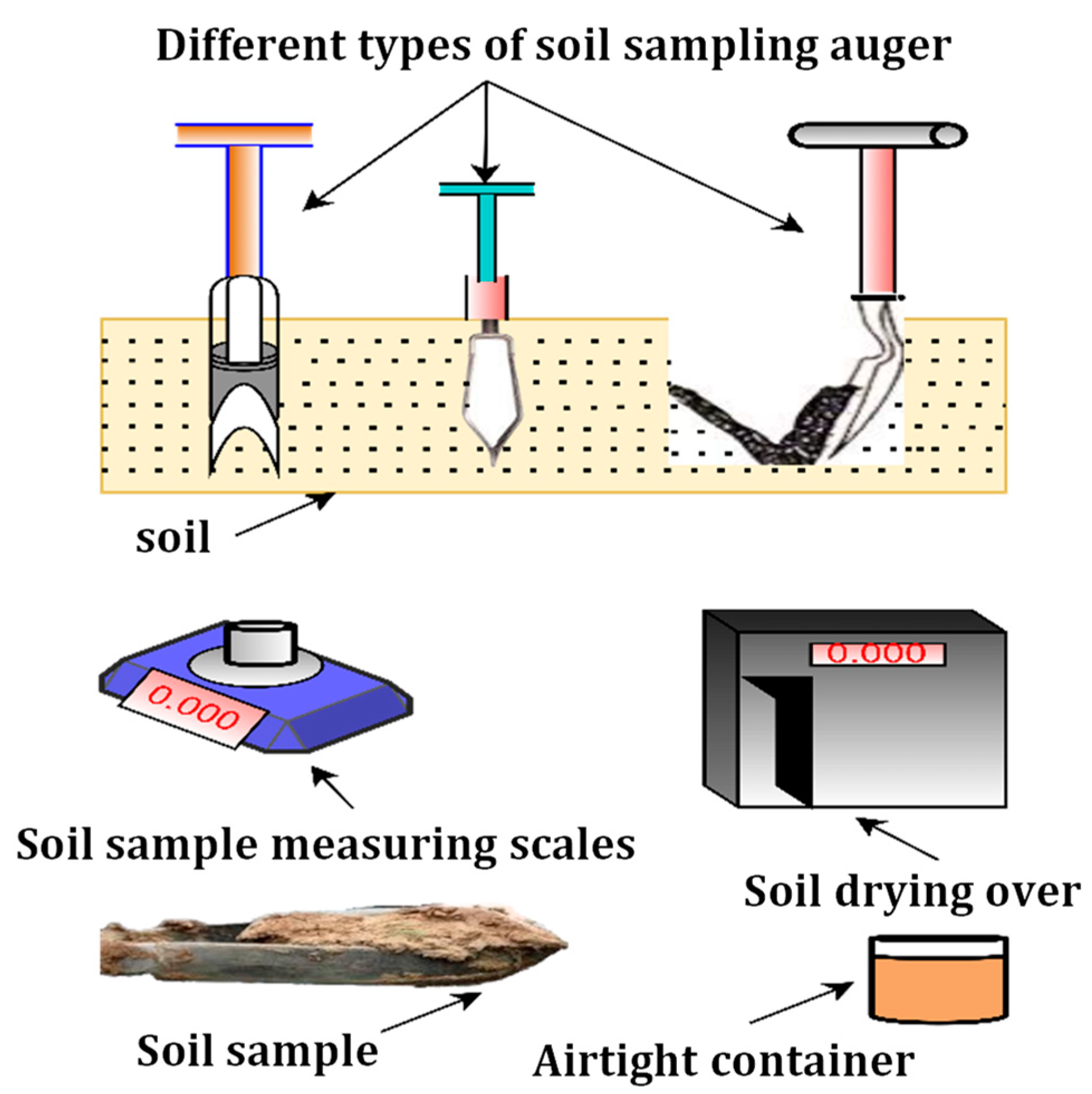
Schematic representation of the components of traditional and

PDF) Using a Partial Sum Method and GPS Tracking Data to Identify Area Restricted Search by Artisanal Fishers at Moored Fish Aggregating Devices in the Commonwealth of Dominica

Typical Failure Assessment Diagram (FAD) indicating safe, failure
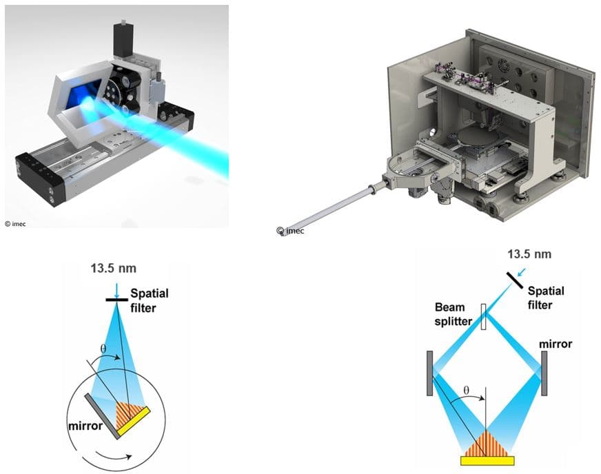
High-NA EUV lithography: the next step after EUVL

David CARLSON, Texas A&M University, Texas, TAMU, Department of Anthropology

Schematics of the flow field for a forward-facing step with two
Using a Partial Sum Method and GPS Tracking Data to Identify Area Restricted Search by Artisanal Fishers at Moored Fish Aggregating Devices in the Commonwealth of Dominica
Recommended for you
 NP LED Night Fishing Light Underwater Night Fishing UAE14 Jul 2023
 Fish Attracting Light Indicator, Attraction Lights Lamp14 Jul 2023
 Tiger Fishing in the Upper Zambezi14 Jul 2023
 Led Light Ocean Fishing Attract Fishing net Vertical Bobber Fishing Float Lights14 Jul 2023
 Deep Sea Fishing in Japan14 Jul 2023
 Salmon Fishing on Lake Ontario - Fatal Attraction Charters14 Jul 2023
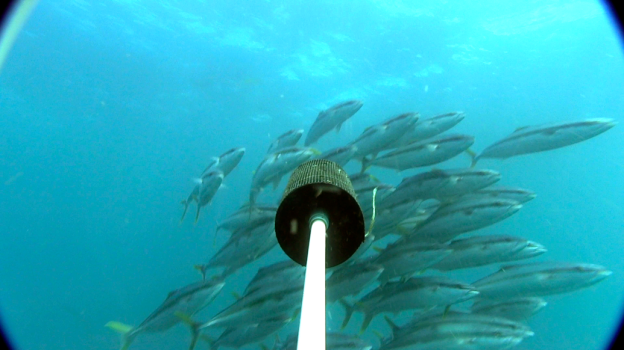 Rules of attraction: enticing pelagic fish to underwater cameras14 Jul 2023
 False Bait Plastic Surface Lure Top Lightweight Fishing Tools with Water Snakehead Bait Bionic Fishing Tools Strong Attraction Simulated Fish Scale14 Jul 2023
 Ba Hang fishing village - a great tourist attraction in Halong Halong Junk Cruise14 Jul 2023
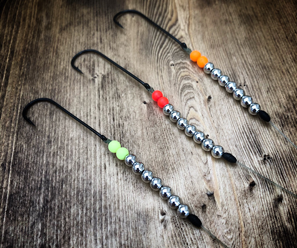 Ideas For Adding Attraction To Your Sea Fishing Hooks - Fishing Maverick14 Jul 2023
You may also like
 Fishing Equipment - Browning / Fishing Equipment14 Jul 2023
 Cheap Jackall Big Backer Soft Vib Sinking Lure 21 grams Shirasu Clear (5761)14 Jul 2023
 Woosir Large Capacity Fishing Rod Bag - 37 Inches / Army Green14 Jul 2023
 Alichino Two Sided Light Weights Foam Insert Fishing Fly Box, Fishing Box For Fly Tying14 Jul 2023
 The Pole, L.L. Bean Bamboo Flyrod14 Jul 2023
 Mikilon Men's And Women's Sports Riding Sunglasses Hd Polarized Driving Sunglasses Black14 Jul 2023
 Daiwa Upgrades the Legendary Certate Spinning Reels14 Jul 2023
 All Purpose Screw Hook in Black Vinyl Coated (20-Pack)14 Jul 2023
 Penn , Garcia mitchel 622 shimano TX1200 Fishing reels14 Jul 2023
 Owner Cultiva ST-31 Stinger Treble14 Jul 2023